Instruments of Microscopy
By the end of this section, you will be able to:
- Identify and describe the parts of a brightfield microscope
- Calculate total magnification for a compound microscope
- Describe the distinguishing features and typical uses for various types of light microscopes, electron microscopes, and scanning probe microscopes
The early pioneers of microscopy opened a window into the invisible world of microorganisms. But microscopy continued to advance in the centuries that followed. In 1830, Joseph Jackson Lister created an essentially modern light microscope. The 20th century saw the development of microscopes that leveraged nonvisible light, such as fluorescence microscopy, which uses an ultraviolet light source, and electron microscopy, which uses short-wavelength electron beams. These advances led to major improvements in magnification, resolution, and contrast. By comparison, the relatively rudimentary microscopes of van Leeuwenhoek and his contemporaries were far less powerful than even the most basic microscopes in use today. In this section, we will survey the broad range of modern microscopic technology and common applications for each type of microscope.
Light Microscopy
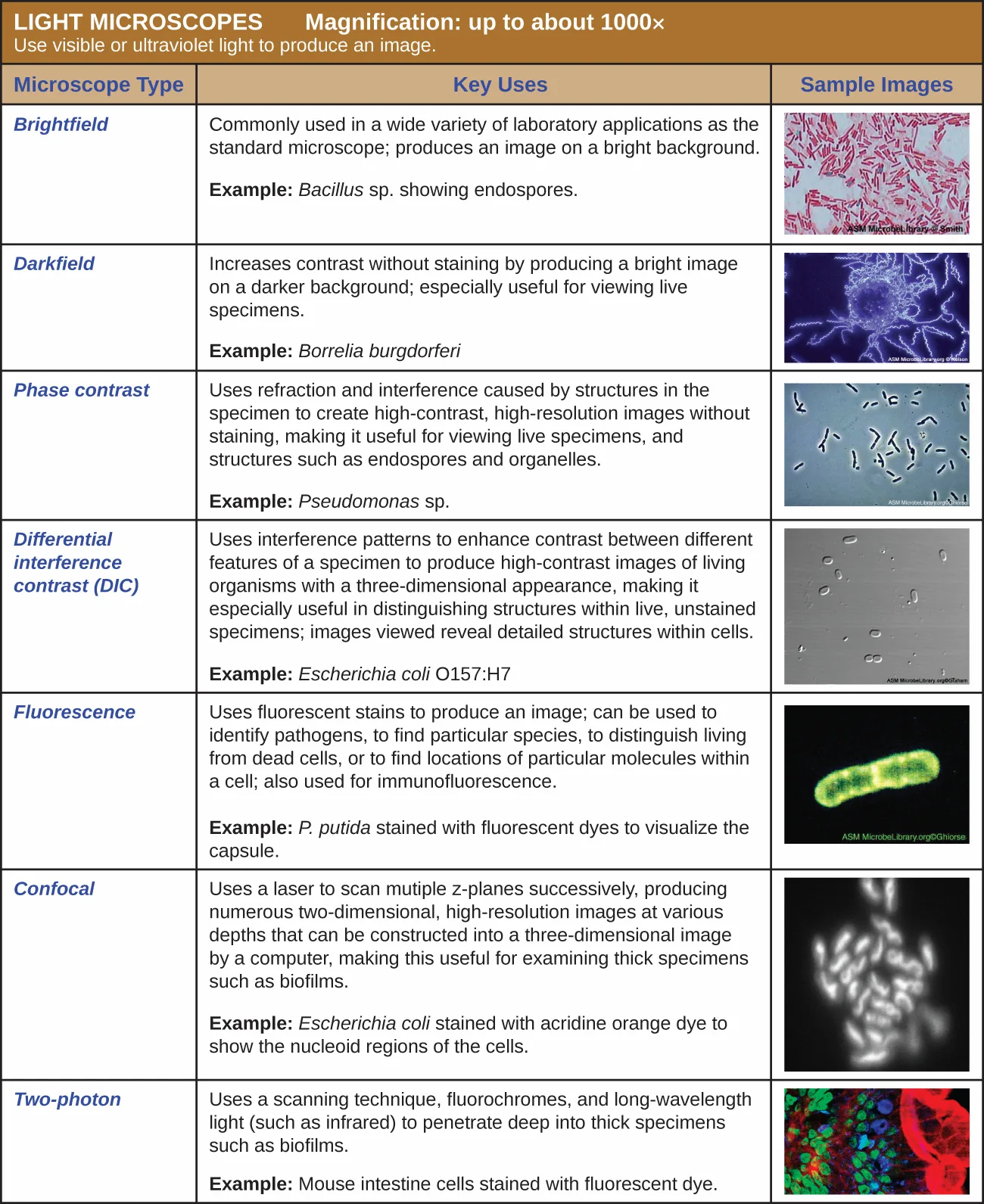
Many types of microscopes fall under the category of light microscopes, which use light to visualize images. Examples of light microscopes include brightfield microscopes, darkfield microscopes, phase-contrast microscopes, differential interference contrast microscopes, fluorescence microscopes, confocal scanning laser microscopes, and two-photon microscopes. These various types of light microscopes can be used to complement each other in diagnostics and research.
Brightfield Microscopes
The brightfield microscope, perhaps the most commonly used type of microscope, is a compound microscope with two or more lenses that produce a dark image on a bright background. Some brightfield microscopes are monocular (having a single eyepiece), though most newer brightfield microscopes are binocular (having two eyepieces), like the one shown below; in either case, each eyepiece contains a lens called an ocular lens. The ocular lenses typically magnify images 10 times (10×). At the other end of the body tube are a set of objective lenses on a rotating nosepiece. The magnification of these objective lenses typically ranges from 4× to 100×, with the magnification for each lens designated on the metal casing of the lens. The ocular and objective lenses work together to create a magnified image. The total magnification is the product of the ocular magnification times the objective magnification:
For example, if a 40× objective lens is selected and the ocular lens is 10×, the total magnification would be
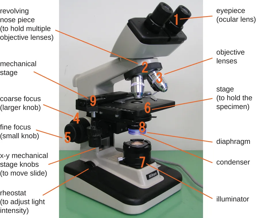
Extended description
Reading top to bottom: the two eyepieces (1) sit atop the body tube; the tube angles down to the revolving nosepiece (2), which holds four objective lenses (3) pointing down at the flat stage (6); a pair of knobs at the stage’s left edge (9) move the slide; below the stage, two stacked lenses (8) are the diaphragm and condenser; on the arm below the stage, a larger coarse-focus knob (4) sits above a smaller fine-focus knob (5); at the base, the illuminator bulb housing (7) sits beside the rheostat dial that dims it.
The item being viewed is called a specimen. The specimen is placed on a glass slide, which is then clipped into place on the stage (a platform) of the microscope. Once the slide is secured, the specimen on the slide is positioned over the light using the x-y mechanical stage knobs. These knobs move the slide on the surface of the stage, but do not raise or lower the stage. Once the specimen is centered over the light, the stage position can be raised or lowered to focus the image. The coarse focusing knob is used for large-scale movements with 4× and 10× objective lenses; the fine focusing knob is used for small-scale movements, especially with 40× or 100× objective lenses.
When images are magnified, they become dimmer because there is less light per unit area of image. Highly magnified images produced by microscopes, therefore, require intense lighting. In a brightfield microscope, this light is provided by an illuminator, which is typically a high-intensity bulb below the stage. Light from the illuminator passes up through condenser lens (located below the stage), which focuses all of the light rays on the specimen to maximize illumination. The position of the condenser can be optimized using the attached condenser focus knob; once the optimal distance is established, the condenser should not be moved to adjust the brightness. If less-than-maximal light levels are needed, the amount of light striking the specimen can be easily adjusted by opening or closing a diaphragm between the condenser and the specimen. In some cases, brightness can also be adjusted using the rheostat, a dimmer switch that controls the intensity of the illuminator.
A brightfield microscope creates an image by directing light from the illuminator at the specimen; this light is differentially transmitted, absorbed, reflected, or refracted by different structures. Different colors can behave differently as they interact with chromophores (pigments that absorb and reflect particular wavelengths of light) in parts of the specimen. Often, chromophores are artificially added to the specimen using stains, which serve to increase contrast and resolution. In general, structures in the specimen will appear darker, to various extents, than the bright background, creating maximally sharp images at magnifications up to about 1000×. Further magnification would create a larger image, but without increased resolution. This allows us to see objects as small as bacteria, which are visible at about 400× or so, but not smaller objects such as viruses.
At very high magnifications, resolution may be compromised when light passes through the small amount of air between the specimen and the lens. This is due to the large difference between the refractive indices of air and glass; the air scatters the light rays before they can be focused by the lens. To solve this problem, a drop of oil can be used to fill the space between the specimen and an oil immersion lens, a special lens designed to be used with immersion oils. Since the oil has a refractive index very similar to that of glass, it increases the maximum angle at which light leaving the specimen can strike the lens. This increases the light collected and, thus, the resolution of the image. A variety of oils can be used for different types of light.
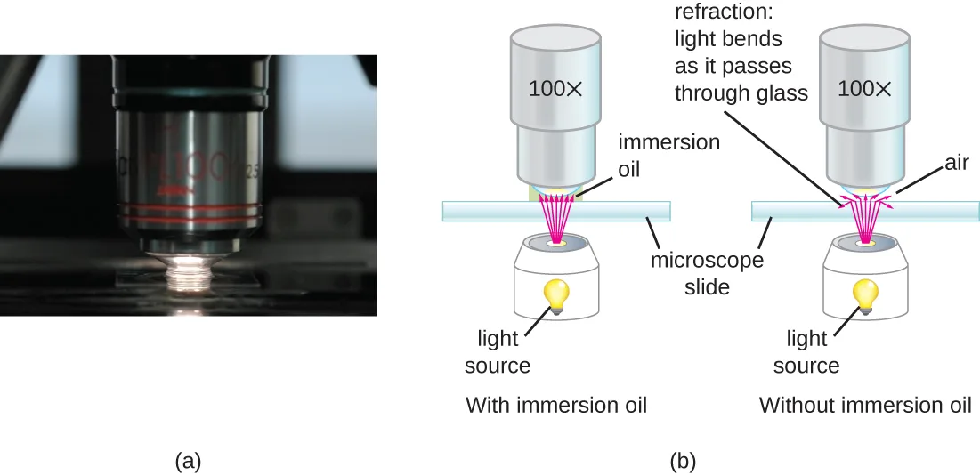
Extended description
Panel (b) shows two diagrams side by side. Left, labeled ‘With immersion oil’: a light source below a microscope slide sends light up through the slide, through a layer of immersion oil, and into a 100× objective lens with the light rays staying close together. Right, labeled ‘Without immersion oil’: the same arrangement without oil, where the light rays bend apart (labeled ‘refraction: light bends as it passes through glass’) as they cross from the glass slide into the air gap below the lens.
Micro Connection. Microscope Maintenance: Best Practices
Even a very powerful microscope cannot deliver high-resolution images if it is not properly cleaned and maintained. Since lenses are carefully designed and manufactured to refract light with a high degree of precision, even a slightly dirty or scratched lens will refract light in unintended ways, degrading the image of the specimen. In addition, microscopes are rather delicate instruments, and great care must be taken to avoid damaging parts and surfaces. Among other things, proper care of a microscope includes the following:
- cleaning the lenses with lens paper
- not allowing lenses to contact the slide (e.g., by rapidly changing the focus)
- protecting the bulb (if there is one) from breakage
- not pushing an objective into a slide
- not using the coarse focusing knob when using the 40× or greater objective lenses
- only using immersion oil with a specialized oil objective, usually the 100× objective
- cleaning oil from immersion lenses after using the microscope
- cleaning any oil accidentally transferred from other lenses
- covering the microscope or placing it in a cabinet when not in use
Link to Learning
Visit the online resource linked below for simulations and demonstrations involving the use of microscopes. Keep in mind that execution of specific techniques and procedures can vary depending on the specific instrument you are using. Thus, it is important to learn and practice with an actual microscope in a laboratory setting under expert supervision.
- University of Delaware’s Virtual Microscope
Darkfield Microscopy
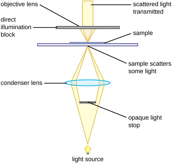
A darkfield microscope is a brightfield microscope that has a small but significant modification to the condenser. A small, opaque disk (about 1 cm in diameter) is placed between the illuminator and the condenser lens. This opaque light stop, as the disk is called, blocks most of the light from the illuminator as it passes through the condenser on its way to the objective lens, producing a hollow cone of light that is focused on the specimen. The only light that reaches the objective is light that has been refracted or reflected by structures in the specimen. The resulting image typically shows bright objects on a dark background.
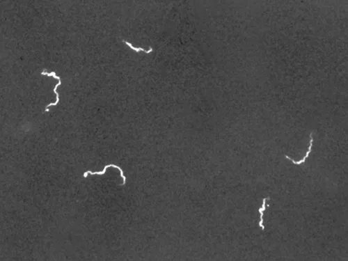
Darkfield microscopy can often create high-contrast, high-resolution images of specimens without the use of stains, which is particularly useful for viewing live specimens that might be killed or otherwise compromised by the stains. For example, thin spirochetes like Treponema pallidum, the causative agent of syphilis, can be best viewed using a darkfield microscope.
Check Your Understanding
Identify the key differences between brightfield and darkfield microscopy by sorting each phrase under the microscope it describes.
Brightfield
Darkfield
Clinical Focus. Part 2
Wound infections like Cindy’s can be caused by many different types of bacteria, some of which can spread rapidly with serious complications. Identifying the specific cause is very important to select a medication that can kill or stop the growth of the bacteria.
After calling a local doctor about Cindy’s case, the camp nurse sends the sample from the wound to the closest medical laboratory. Unfortunately, since the camp is in a remote area, the nearest lab is small and poorly equipped. A more modern lab would likely use other methods to culture, grow, and identify the bacteria, but in this case, the technician decides to make a wet mount from the specimen and view it under a brightfield microscope. In a wet mount, a small drop of water is added to the slide, and a cover slip is placed over the specimen to keep it in place before it is positioned under the objective lens.
Under the brightfield microscope, the technician can barely see the bacteria cells because they are nearly transparent against the bright background. To increase contrast, the technician inserts an opaque light stop above the illuminator. The resulting darkfield image clearly shows that the bacteria cells are spherical and grouped in clusters, like grapes.
- Why is it important to identify the shape and growth patterns of cells in a specimen?
- What other types of microscopy could be used effectively to view this specimen?
The case continues in Staining Microscopic Specimens. The case began in The Properties of Light.
Phase-Contrast Microscopes
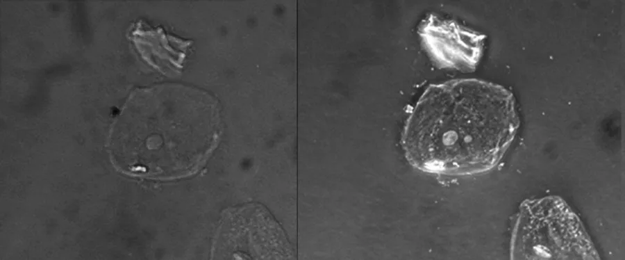
Phase-contrast microscopes use refraction and interference caused by structures in a specimen to create high-contrast, high-resolution images without staining. It is the oldest and simplest type of microscope that creates an image by altering the wavelengths of light rays passing through the specimen. To create altered wavelength paths, an annular stop is used in the condenser. The annular stop produces a hollow cone of light that is focused on the specimen before reaching the objective lens. The objective contains a phase plate containing a phase ring. As a result, light traveling directly from the illuminator passes through the phase ring while light refracted or reflected by the specimen passes through the plate. This causes waves traveling through the ring to be about one-half of a wavelength out of phase with those passing through the plate. Because waves have peaks and troughs, they can add together (if in phase together) or cancel each other out (if out of phase). When the wavelengths are out of phase, wave troughs will cancel out wave peaks, which is called destructive interference. Structures that refract light then appear dark against a bright background of only unrefracted light. More generally, structures that differ in features such as refractive index will differ in levels of darkness.
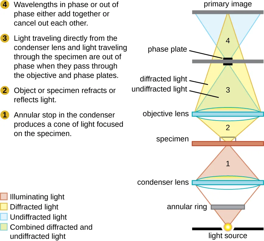
Extended description
The diagram runs bottom to top: a light source sits below an annular ring, which shapes the light into a cone (stage 1, illuminating light) aimed through a condenser lens at the specimen. The specimen (stage 2) refracts or reflects part of the light, splitting it into undiffracted light and diffracted light. Both pass up through the objective lens and a phase plate (stage 3), which puts the two out of phase with each other. They recombine at the primary image (stage 4), where a color key marks illuminating light, diffracted light, undiffracted light, and the combined diffracted-and-undiffracted light that forms the final image.
Because it increases contrast without requiring stains, phase-contrast microscopy is often used to observe live specimens. Certain structures, such as organelles in eukaryotic cells and endospores in prokaryotic cells, are especially well visualized with phase-contrast microscopy.
Differential Interference Contrast Microscopes
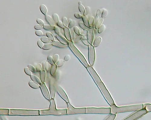
Differential interference contrast (DIC) microscopes (also known as Nomarski optics) are similar to phase-contrast microscopes in that they use interference patterns to enhance contrast between different features of a specimen. In a DIC microscope, two beams of light are created in which the direction of wave movement (polarization) differs. Once the beams pass through either the specimen or specimen-free space, they are recombined and effects of the specimens cause differences in the interference patterns generated by the combining of the beams. This results in high-contrast images of living organisms with a three-dimensional appearance. These microscopes are especially useful in distinguishing structures within live, unstained specimens.
Check Your Understanding
What are some advantages of phase-contrast and DIC microscopy? Sort each phrase under the microscope it describes.
Phase contrast
DIC
Fluorescence Microscopes
A fluorescence microscope uses fluorescent chromophores called fluorochromes, which are capable of absorbing energy from a light source and then emitting this energy as visible light. Fluorochromes include naturally fluorescent substances (such as chlorophylls) as well as fluorescent stains that are added to the specimen to create contrast. Dyes such as Texas red and FITC are examples of fluorochromes. Other examples include the nucleic acid dyes 4’,6’-diamidino-2-phenylindole (DAPI) and acridine orange.
The microscope transmits an excitation light, generally a form of EMR with a short wavelength, such as ultraviolet or blue light, toward the specimen; the chromophores absorb the excitation light and emit visible light with longer wavelengths. The excitation light is then filtered out (in part because ultraviolet light is harmful to the eyes) so that only visible light passes through the ocular lens. This produces an image of the specimen in bright colors against a dark background.
Fluorescence microscopes are especially useful in clinical microbiology. They can be used to identify pathogens, to find particular species within an environment, or to find the locations of particular molecules and structures within a cell. Approaches have also been developed to distinguish living from dead cells using fluorescence microscopy based upon whether they take up particular fluorochromes. Sometimes, multiple fluorochromes are used on the same specimen to show different structures or features.
One of the most important applications of fluorescence microscopy is a technique called immunofluorescence, which is used to identify certain disease-causing microbes by observing whether antibodies bind to them. (Antibodies are protein molecules produced by the immune system that attach to specific pathogens to kill or inhibit them.) There are two approaches to this technique: direct immunofluorescence assay (DFA) and indirect immunofluorescence assay (IFA). In DFA, specific antibodies (e.g., those that the target the rabies virus) are stained with a fluorochrome. If the specimen contains the targeted pathogen, one can observe the antibodies binding to the pathogen under the fluorescent microscope. This is called a primary antibody stain because the stained antibodies attach directly to the pathogen.
In IFA, secondary antibodies are stained with a fluorochrome rather than primary antibodies. Secondary antibodies do not attach directly to the pathogen, but they do bind to primary antibodies. When the unstained primary antibodies bind to the pathogen, the fluorescent secondary antibodies can be observed binding to the primary antibodies. Thus, the secondary antibodies are attached indirectly to the pathogen. Since multiple secondary antibodies can often attach to a primary antibody, IFA increases the number of fluorescent antibodies attached to the specimen, making it easier to visualize features in the specimen.
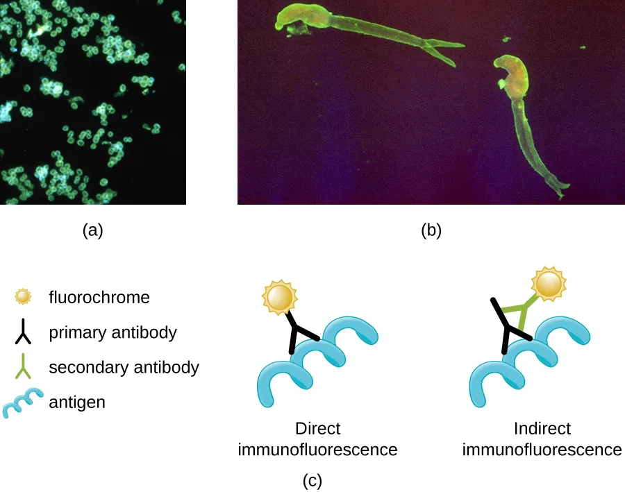
Extended description
Panel (c)’s key shows a glowing circle for fluorochrome, a black Y-shape for primary antibody, a green Y-shape for secondary antibody, and a wavy blue shape for antigen. In the direct immunofluorescence diagram, a fluorochrome sits at the tip of a primary antibody, which is bound directly to the antigen. In the indirect immunofluorescence diagram, the fluorochrome sits at the tip of a secondary antibody, which is bound to a primary antibody, which is in turn bound to the antigen.
Check Your Understanding
Why must fluorochromes be used to examine a specimen under a fluorescence microscope?
Think about what a fluorescence microscope transmits toward the specimen, and what has to absorb and re-emit that light for an image to form.Confocal Microscopes
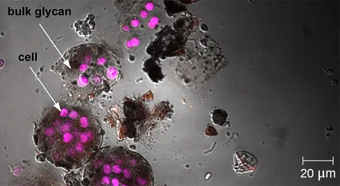
Whereas other forms of light microscopy create an image that is maximally focused at a single distance from the observer (the depth, or z-plane), a confocal microscope uses a laser to scan multiple z-planes successively. This produces numerous two-dimensional, high-resolution images at various depths, which can be constructed into a three-dimensional image by a computer. As with fluorescence microscopes, fluorescent stains are generally used to increase contrast and resolution. Image clarity is further enhanced by a narrow aperture that eliminates any light that is not from the z-plane. Confocal microscopes are thus very useful for examining thick specimens such as biofilms, which can be examined alive and unfixed.
Link to Learning
Explore a rotating three-dimensional view of a biofilm as observed under a confocal microscope. After navigating to the webpage, click the “play” button to launch the video.
Two-Photon Microscopes
While the original fluorescent and confocal microscopes allowed better visualization of unique features in specimens, there were still problems that prevented optimum visualization. The effective sensitivity of fluorescence microscopy when viewing thick specimens was generally limited by out-of-focus flare, which resulted in poor resolution. This limitation was greatly reduced in the confocal microscope through the use of a confocal pinhole to reject out-of-focus background fluorescence with thin (<1 µm), unblurred optical sections. However, even the confocal microscopes lacked the resolution needed for viewing thick tissue samples. These problems were resolved with the development of the two-photon microscope, which uses a scanning technique, fluorochromes, and long-wavelength light (such as infrared) to visualize specimens. The low energy associated with the long-wavelength light means that two photons must strike a location at the same time to excite the fluorochrome. The low energy of the excitation light is less damaging to cells, and the long wavelength of the excitation light more easily penetrates deep into thick specimens. This makes the two-photon microscope useful for examining living cells within intact tissues—brain slices, embryos, whole organs, and even entire animals.
Currently, use of two-photon microscopes is limited to advanced clinical and research laboratories because of the high costs of the instruments. A single two-photon microscope typically costs between $300,000 and $500,000, and the lasers used to excite the dyes used on specimens are also very expensive. However, as technology improves, two-photon microscopes may become more readily available in clinical settings.
Check Your Understanding
What types of specimens are best examined using confocal or two-photon microscopy? Sort each phrase under the microscope it describes.
Confocal microscope
Two-photon microscope
Electron Microscopy
The maximum theoretical resolution of images created by light microscopes is ultimately limited by the wavelengths of visible light. Most light microscopes can only magnify 1000×, and a few can magnify up to 1500×, but this does not begin to approach the magnifying power of an electron microscope (EM), which uses short-wavelength electron beams rather than light to increase magnification and resolution.
Electrons, like electromagnetic radiation, can behave as waves, but with wavelengths of 0.005 nm, they can produce much better resolution than visible light. An EM can produce a sharp image that is magnified up to 100,000×. Thus, EMs can resolve subcellular structures as well as some molecular structures (e.g., single strands of DNA); however, electron microscopy cannot be used on living material because of the methods needed to prepare the specimens.
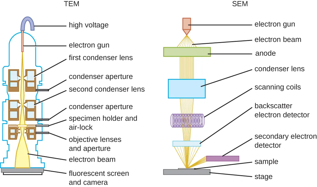
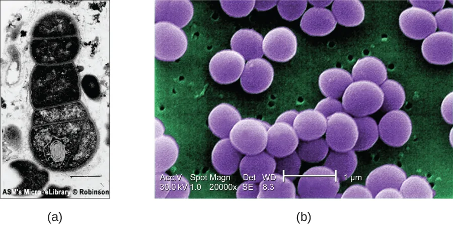
There are two basic types of EM: the transmission electron microscope (TEM) and the scanning electron microscope (SEM). The TEM is somewhat analogous to the brightfield light microscope in terms of the way it functions. However, it uses an electron beam from above the specimen that is focused using a magnetic lens (rather than a glass lens) and projected through the specimen onto a detector. Electrons pass through the specimen, and then the detector captures the image.
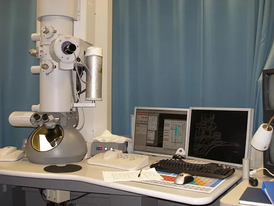
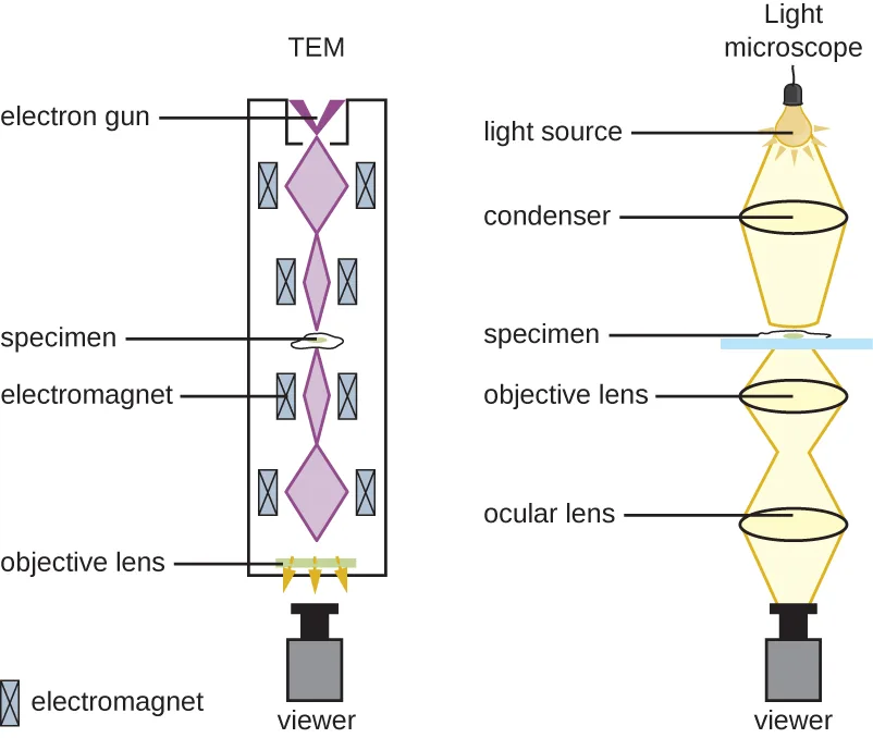
For electrons to pass through the specimen in a TEM, the specimen must be extremely thin (20–100 nm thick). The image is produced because of varying opacity in various parts of the specimen. This opacity can be enhanced by staining the specimen with materials such as heavy metals, which are electron dense. TEM requires that the beam and specimen be in a vacuum and that the specimen be very thin and dehydrated. The specific steps needed to prepare a specimen for observation under an EM are discussed in detail in the next section.
SEMs form images of surfaces of specimens, usually from electrons that are knocked off of specimens by a beam of electrons. This can create highly detailed images with a three-dimensional appearance that are displayed on a monitor. Typically, specimens are dried and prepared with fixatives that reduce artifacts, such as shriveling, that can be produced by drying, before being sputter-coated with a thin layer of metal such as gold. Whereas transmission electron microscopy requires very thin sections and allows one to see internal structures such as organelles and the interior of membranes, scanning electron microscopy can be used to view the surfaces of larger objects (such as a pollen grain) as well as the surfaces of very small samples. Some EMs can magnify an image up to 2,000,000× (“JEM-ARM200F Transmission Electron Microscope,” JEOL USA Inc).
To expand both the resolution and the types of materials that could be examined, Pratibha L. Gai and Edward D. Boyes invented the environmental transmission electron microscope (ETEM). The device advanced the standard electron microscope by incorporating a gas-filled chamber in which a wider array of substances could be contained. Thus researchers could observe actual reactions taking place at incredible magnifications. Gai later improved on her work by creating the environmental scanning transmission electron microscope (ESTEM), which has even greater resolving power. Gai herself was the first person to ever see individual atoms interacting.
Extended description
The TEM column, top to bottom: high voltage line, electron gun, first condenser lens with its aperture, second condenser lens with its aperture, specimen holder and air lock, objective lens and aperture, fluorescent screen and camera. The SEM column, top to bottom: electron gun, electron beam narrowing through an anode, condenser lens, scanning coils, then the beam striking a sample on a stage; a backscatter electron detector sits directly above the sample and a secondary electron detector sits off to one side.
Check Your Understanding
What are some advantages and disadvantages of electron microscopy, as opposed to light microscopy, for examining microbiological specimens?
Show model answer
Did your answer mention:
What kinds of specimens are best examined using TEM? SEM? Sort each phrase under the microscope it describes.
Transmission electron microscope
Scanning electron microscope
Micro Connection. Using Microscopy to Study Biofilms
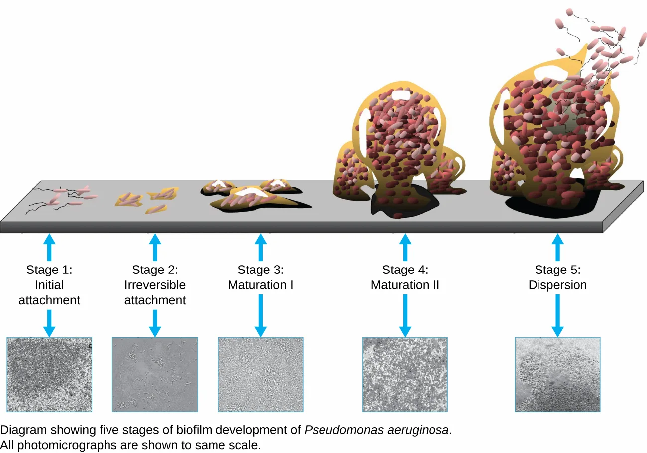
A biofilm is a complex community of one or more microorganism species, typically forming as a slimy coating attached to a surface because of the production of an extrapolymeric substance (EPS) that attaches to a surface or at the interface between surfaces (e.g., between air and water). In nature, biofilms are abundant and frequently occupy complex niches within ecosystems. In medicine, biofilms can coat medical devices and exist within the body. Because they possess unique characteristics, such as increased resistance against the immune system and to antimicrobial drugs, biofilms are of particular interest to microbiologists and clinicians alike.
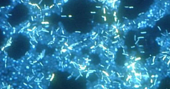
Because biofilms are thick, they cannot be observed very well using light microscopy; slicing a biofilm to create a thinner specimen might kill or disturb the microbial community. Confocal microscopy provides clearer images of biofilms because it can focus on one z-plane at a time and produce a three-dimensional image of a thick specimen. Fluorescent dyes can be helpful in identifying cells within the matrix. Additionally, techniques such as immunofluorescence and fluorescence in situ hybridization (FISH), in which fluorescent probes are used to bind to DNA, can be used.
Electron microscopy can be used to observe biofilms, but only after dehydrating the specimen, which produces undesirable artifacts and distorts the specimen. In addition to these approaches, it is possible to follow water currents through the shapes (such as cones and mushrooms) of biofilms, using video of the movement of fluorescently coated beads.
Extended description
Left to right along the surface: Stage 1 shows a handful of scattered rod cells with wavy flagella. Stage 2 shows several small flat clumps of cells. Stage 3 shows the clumps thickened into irregular low mounds studded with cells. Stage 4 shows tall, hollow, mushroom-shaped towers densely packed with pink and maroon cells. Stage 5 shows a similar tower with cells and flagella streaming away from its top. Below each stage, a matching grayscale photomicrograph shows the same progression from scattered dots to a dense, textured mass.
Scanning Probe Microscopy
A scanning probe microscope does not use light or electrons, but rather very sharp probes that are passed over the surface of the specimen and interact with it directly. This produces information that can be assembled into images with magnifications up to 100,000,000×. Such large magnifications can be used to observe individual atoms on surfaces. To date, these techniques have been used primarily for research rather than for diagnostics.
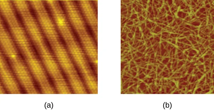
There are two types of scanning probe microscope: the scanning tunneling microscope (STM) and the atomic force microscope (AFM). An STM uses a probe that is passed just above the specimen as a constant voltage bias creates the potential for an electric current between the probe and the specimen. This current occurs via quantum tunneling of electrons between the probe and the specimen, and the intensity of the current is dependent upon the distance between the probe and the specimen. The probe is moved horizontally above the surface and the intensity of the current is measured. Scanning tunneling microscopy can effectively map the structure of surfaces at a resolution at which individual atoms can be detected.
Similar to an STM, AFMs have a thin probe that is passed just above the specimen. However, rather than measuring variations in the current at a constant height above the specimen, an AFM establishes a constant current and measures variations in the height of the probe tip as it passes over the specimen. As the probe tip is passed over the specimen, forces between the atoms (van der Waals forces, capillary forces, chemical bonding, electrostatic forces, and others) cause it to move up and down. Deflection of the probe tip is determined and measured using Hooke’s law of elasticity, and this information is used to construct images of the surface of the specimen with resolution at the atomic level.
The table below summarizes the microscopy techniques for light microscopes, electron microscopes, and scanning probe microscopes, respectively.
Check Your Understanding
Which has higher magnification, a light microscope or a scanning probe microscope?
Compare the maximum magnification stated for light microscopes with the maximum stated for scanning probe microscopes.Name one advantage and one limitation of scanning probe microscopy.
Show model answer
Did your answer mention:
Light microscopes — use visible or ultraviolet light to produce an image; magnification up to about 1000×.
| Microscope type | Key uses | Example organism |
|---|---|---|
| Brightfield | Commonly used in a wide variety of laboratory applications as the standard microscope; produces an image on a bright background. | Bacillus sp. showing endospores |
| Darkfield | Increases contrast without staining by producing a bright image on a darker background; especially useful for viewing live specimens. | Borrelia burgdorferi |
| Phase contrast | Uses refraction and interference caused by structures in the specimen to create high-contrast, high-resolution images without staining, making it useful for viewing live specimens, and structures such as endospores and organelles. | Pseudomonas sp. |
| Differential interference contrast (DIC) | Uses interference patterns to enhance contrast between different features of a specimen to produce high-contrast images of living organisms with a three-dimensional appearance, making it especially useful in distinguishing structures within live, unstained specimens; images viewed reveal detailed structures within cells. | Escherichia coli O157:H7 |
| Fluorescence | Uses fluorescent stains to produce an image; can be used to identify pathogens, to find particular species, to distinguish living from dead cells, or to find the locations of particular molecules within a cell; also used for immunofluorescence. | P. putida stained with fluorescent dyes to visualize the capsule |
| Confocal | Uses a laser to scan multiple z-planes successively, producing numerous two-dimensional, high-resolution images at various depths that can be constructed into a three-dimensional image by a computer, making this useful for examining thick specimens such as biofilms. | Escherichia coli stained with acridine orange dye to show the nucleoid regions of the cells |
| Two-photon | Uses a scanning technique, fluorochromes, and long-wavelength light (such as infrared) to penetrate deep into thick specimens such as biofilms. | Mouse intestine cells stained with fluorescent dye |
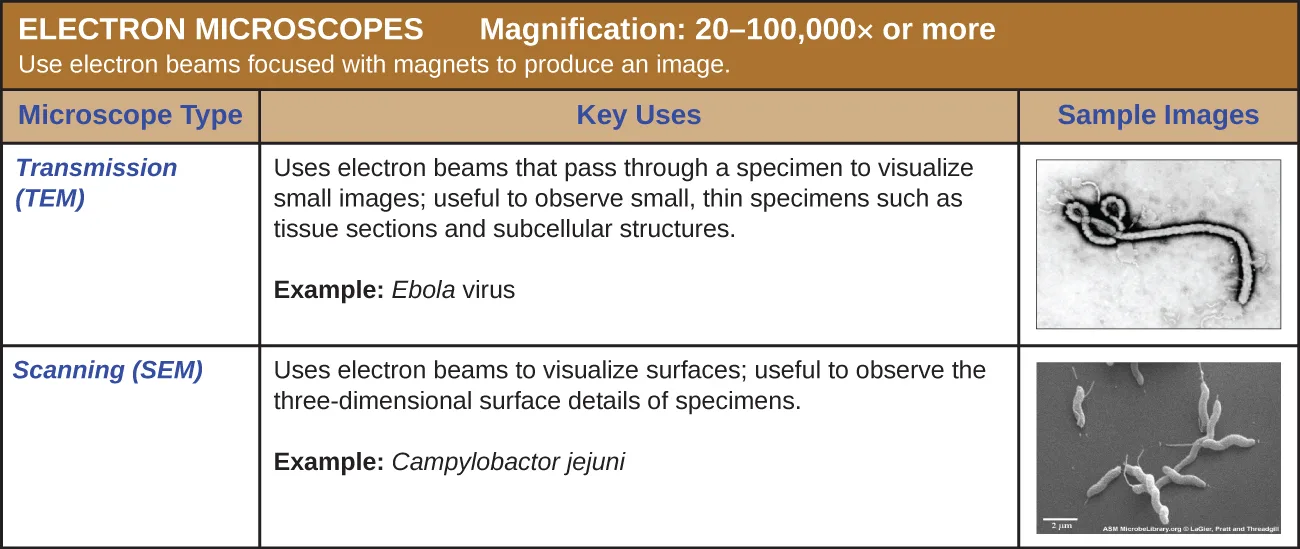
Electron microscopes — use electron beams focused with magnets to produce an image; magnification 20–100,000× or more.
| Microscope type | Key uses | Example organism |
|---|---|---|
| Transmission (TEM) | Uses electron beams that pass through a specimen to visualize small images; useful to observe small, thin specimens such as tissue sections and subcellular structures. | Ebola virus |
| Scanning (SEM) | Uses electron beams to visualize surfaces; useful to observe the three-dimensional surface details of specimens. | Campylobacter jejuni |
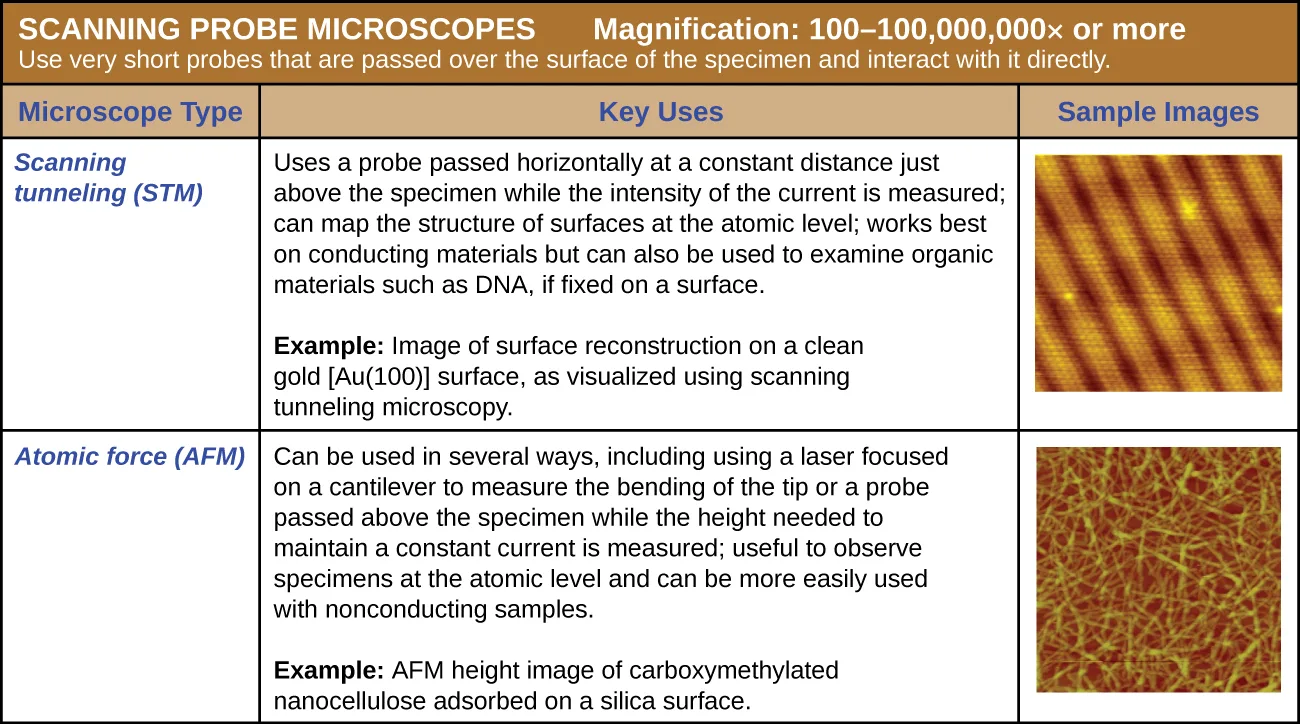
Scanning probe microscopes — use very sharp probes that are passed over the surface of the specimen and interact with it directly; magnification 100–100,000,000× or more.
| Microscope type | Key uses | Example organism |
|---|---|---|
| Scanning tunneling (STM) | Uses a probe passed horizontally at a constant distance just above the specimen while the intensity of the current is measured; can map the structure of surfaces at the atomic level; works best on conducting materials but can also be used to examine organic materials such as DNA if fixed on a surface. | Surface reconstruction on a clean gold [Au(100)] surface |
| Atomic force (AFM) | Can be used in several ways, including using a laser focused on a cantilever to measure the bending of the tip, or a probe passed above the specimen while the height needed to maintain a constant current is measured; useful to observe specimens at the atomic level and can be more easily used with nonconducting samples. | Carboxymethylated nanocellulose adsorbed on a silica surface |
Summary
- Numerous types of microscopes use various technologies to generate micrographs. Most are useful for a particular type of specimen or application.
- Light microscopy uses lenses to focus light on a specimen to produce an image. Commonly used light microscopes include brightfield, darkfield, phase-contrast, differential interference contrast, fluorescence, confocal, and two-photon microscopes.
- Electron microscopy focuses electrons on the specimen using magnets, producing much greater magnification than light microscopy. The transmission electron microscope (TEM) and scanning electron microscope (SEM) are two common forms.
- Scanning probe microscopy produces images of even greater magnification by measuring feedback from sharp probes that interact with the specimen. Probe microscopes include the scanning tunneling microscope (STM) and the atomic force microscope (AFM).
Key terms
- brightfield microscope — a compound light microscope with two lenses; it produces a dark image on a bright background.
- monocular — having a single eyepiece.
- binocular — having two eyepieces.
- ocular lens — on a microscope, the lens closest to the eye (also called an eyepiece).
- objective lenses — on a light microscope, the lenses closest to the specimen, typically located at the ends of turrets.
- total magnification — in a light microscope is a value calculated by multiplying the magnification of the ocular by the magnification of the objective lenses.
- stage — the platform of a microscope on which slides are placed.
- x-y mechanical stage knobs — knobs on a microscope that are used to adjust the position of the specimen on the stage surface, generally to center it directly above the light.
- coarse focusing knob — a knob on a microscope that produces relatively large movements to adjust focus.
- fine focusing knob — a knob on a microscope that produces relatively small movements to adjust focus.
- illuminator — the light source on a microscope.
- condenser lens — a lens on a microscope that focuses light from the light source onto the specimen.
- diaphragm — a component of a microscope; typically consists of a disk under the stage with holes of various sizes; can be adjusted to allow more or less light from the light source to reach the specimen.
- rheostat — a dimmer switch that controls the intensity of the illuminator on a light microscope.
- chromophores — pigments that absorb and reflect particular wavelengths of light (giving them a color).
- oil immersion lens — a special objective lens on a microscope designed to be used with immersion oil to improve resolution.
- darkfield microscope — a compound light microscope that produces a bright image on a dark background; typically a modified brightfield microscope.
- phase-contrast microscope — a light microscope that uses an annular stop and annular plate to increase contrast.
- differential interference contrast (DIC) microscopes — light microscopes that create high-contrast images of live, unstained specimens by combining two beams of light whose polarization differs, then recombining them so that interference between the beams reveals differences between the specimen’s structures.
- fluorescence microscope — a microscope that uses natural fluorochromes or fluorescent stains to increase contrast.
- fluorochromes — chromophores that fluoresce (absorb and then emit light).
- immunofluorescence — a technique that uses a fluorescence microscope and antibody-specific fluorochromes to determine the presence of specific pathogens in a specimen.
- confocal microscope — a scanning laser microscope that uses fluorescent dyes and excitation lasers to create three-dimensional images.
- two-photon microscope — a microscope that uses long-wavelength or infrared light to fluoresce fluorochromes in the specimen.
- electron microscope — a type of microscope that uses short-wavelength electron beams rather than light to increase magnification and resolution.
- transmission electron microscope (TEM) — a type of electron microscope that uses an electron beam, focused with magnets, that passes through a thin specimen.
- scanning electron microscope (SEM) — a type of electron microscope that bounces electrons off of the specimen, forming an image of the surface.
- scanning probe microscope — a microscope that uses a probe that travels across the surface of a specimen at a constant distance while the current, which is sensitive to the size of the gap, is measured.
- scanning tunneling microscope — a microscope that uses a probe that is passed just above the specimen as a constant voltage bias creates the potential for an electric current between the probe and the specimen.
- atomic force microscope — a scanning probe microscope that uses a thin probe that is passed just above the specimen to measure forces between the atoms and the probe.
Practice
Identify and describe the parts of a brightfield microscope
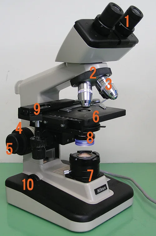
Label each component of the brightfield microscope shown above.
Show model answer
Did your answer mention:
What is the function of the condenser in a brightfield microscope?
Think about what happens to the light rays from the illuminator after they pass through the condenser lens, on their way to the specimen.When focusing a light microscope, why is it best to adjust the focus using the coarse focusing knob before using the fine focusing knob?
Show model answer
Did your answer mention:
You need to identify structures within a cell using a microscope. However, the image appears very blurry even though you have a high magnification. What are some things that you could try to improve the resolution of the image? Describe the most basic factors that affect resolution when you first put the slide onto the stage; then consider more specific factors that could affect resolution for 40× and 100× lenses.
Show model answer
Did your answer mention:
A component of a microscope that typically consists of a disk with holes of various sizes and can be adjusted to control how much light from the light source reaches the specimen is called a ________.
It sits between the condenser and the specimen and is a separate control from the rheostat, which dims the illuminator itself.Calculate total magnification for a compound microscope
What is the total magnification of a specimen that is being viewed with a standard ocular lens and a 40× objective lens?
Standard ocular lenses magnify 10 times; multiply that by the stated power of the 40× lens named in the question.In a light microscope, the value calculated by multiplying the magnification of the ocular lens by the magnification of the objective lens is called ________.
This is the combined magnifying power of both lenses working together, not either lens’s power alone.Total magnification in a compound microscope is calculated by multiplying the magnification of the ocular lens by the magnification of the ________.
This is the lens closest to the specimen, mounted on the rotating nosepiece — not the lens the viewer looks through.Describe the distinguishing features and typical uses for various types of light microscopes, electron microscopes, and scanning probe microscopes
Which would be the best choice for viewing internal structures of a living protist such as a Paramecium?
Think about which of these creates high-contrast images of live, unstained specimens without an electron beam that would kill the cell.Which type of microscope is especially useful for viewing thick structures such as biofilms?
Think about which microscope scans successive z-planes and reconstructs them into a three-dimensional image.Which type of microscope would be the best choice for viewing very small surface structures of a cell?
Think about which microscope images the surface of a specimen, rather than its interior, using an electron beam.What type of microscope uses an annular stop?
This device sits in the condenser; think about which microscope type relies on interference between light that passed through the specimen and light that did not.What type of microscope uses a cone of light so that light only hits the specimen indirectly, producing a light image on a dark background?
Think about which microscope type increases contrast without staining by changing what the condenser lets through.Chromophores that absorb and then emit light are called ________.
Fluorescence microscopy takes its name from this class of pigment.In a(n) ________ microscope, a probe located just above the specimen moves up and down in response to forces between the atoms and the tip of the probe.
This scanning probe microscope holds the current constant and measures the probe’s vertical movement, unlike the type that holds height constant and measures current.Sort each feature of the scanning probe microscopes table under the microscope it describes.
STM
AFM
This section is adapted from Microbiology, Section 2.3: Instruments of Microscopy by Nina Parker, Mark Schneegurt, Anh-Hue Thi Tu, Philip Lister, Brian M. Forster, and OpenStax, © OpenStax, licensed under CC BY-NC-SA 4.0. Access the original for free at openstax.org. Changes: figures re-encoded as WebP with kind set explicitly on every one after inspecting the artwork (photo for every micrograph and annotated photograph, diagram for the Oil Lens, Darkfield, Phase-Contrast, Direct/Indirect Immunofluorescence, TEM-vs-light, electron-microscope schematic, and Biofilms figures, each of which has at least one genuinely drawn panel); several source alts rewritten to describe what the image actually shows, and two corrected against the artwork — the transmission-electron-microscope photo shows only one instrument, not the two the source alt describes, and the Stainless-Steel Biofilm micrograph has a dark blue background with rod-shaped cells, not the “black background” and “rectangles” the source alt describes; the source alt for the light-microscope summary table also silently drops its Two-photon row and misattributes that row’s mouse-intestine example image to Confocal instead — both reported as source-alt defects, and the table below transcribes all seven rows from the table image itself, with the Confocal row’s own example (Escherichia coli stained with acridine orange) and a separate Two-photon row restored; a longdesc added for every figure that is a multi-step or multi-part process diagram (Oil Lens, Phase-Contrast, Direct/Indirect Immunofluorescence diagram, electron-microscope schematic, Biofilms, and the labeled brightfield photo); the three summary-table images (Light, Electron, and Scanning-Probe Microscopes) each transcribed as a Markdown table from the table image, checked against the PDF page, with the source image kept immediately after as a mediafigure for its sample micrographs only (the Electron Microscopes table image and its source alt both print “Campylobactor jejuni”; the transcribed table prints Campylobacter jejuni, reported as a source defect); feature boxes rendered as callouts; of the eight Check Your Understanding bullets across six boxes, six (brightfield vs. darkfield; phase-contrast vs. DIC; why fluorochromes are needed; confocal vs. two-photon specimens; light- vs. scanning-probe magnification; and TEM vs. SEM specimens, a sort-into-bins item built from the Electron Microscopes table) are now graded — five sortbins and one multiplechoice — from this section’s own sentences and tables (6 Check Your Understanding questions graded from the module’s own sentences or tables rather than answered in prose; the source prints no key for them), and two (electron microscopy’s advantages and disadvantages, and scanning probe microscopy’s advantage and limitation) remain body self-checks with model answers and rubrics assembled from this section’s own preceding text, because the module states only one advantage-and-disadvantage pair for each and no further distinguishing phrases exist to fill out a sort-into-bins item (the Electron Microscopy and Scanning Probe Microscopy boxes each print two distinct bullets, not a repeated stem, so neither needed rewording); a sort-into-bins item built from the Scanning Probe Microscopes table is added to the Practice group for the third objective, since no page item asked the STM/AFM distinction the table’s Key uses column draws (conducting vs. nonconducting samples, and the cantilever-laser vs. quantum-tunneling detection each uses); the Clinical Focus box’s “Jump to the next / Go back to the previous Clinical Focus box” links replaced with two plain sentences linking to Sections 2.4 and 2.1; the term “Differential interference contrast (DIC) microscopes” has no Glossary appendix entry, so its Key terms meaning is written from this section’s own defining sentence (1 of 30 definitions taken from the defining sentence; the other 29 are from the Glossary appendix); the end-of-section Multiple Choice, Fill in the Blank, Short Answer, and Critical Thinking questions adapted into the closing interactive Practice block, sorted under the objective each supports, using all twelve source items; the Short Answer “Art Connection” labeling task adapted into a mediafigure (an author-written caption, since the source prints none, describing only the numbered call-outs present rather than naming the parts) followed by a self-check whose model answer and rubric map each number to the part named in the Brightfield Microscopes discussion above; of the section’s four remaining unkeyed Short Answer and Critical Thinking Practice items, one (the function of the condenser) is now a multiplechoice graded from this section’s own sentence (1 of the source’s unkeyed Short Answer questions is graded from the module’s own sentence rather than answered in prose; the source prints no key for it), and model answers for the other Short Answer question, the two Critical Thinking questions, and the two remaining Check Your Understanding self-checks are written from this section’s own text, because the source prints no answer key for any of them; each objective group also received one filler item built strictly from this section’s own text with no new claim, because none of the twelve source items is both auto-graded and about the parts of a brightfield microscope or about the total-magnification calculation specifically: a term-recall textin (“diaphragm”) for the first objective, and a term-recall textin (“total magnification”) plus a select-the-term multiplechoice (“objective lens”) built from the total-magnification sentence for the second; key terms compiled from the module’s 30 defined terms and the book’s Glossary appendix.